
Many individuals back away from any type of electrical problem, repair or installation.
Yet working with electricity, to make an electrical device such as a light go on or off is very simple if you follow some basic guidelines and absorb the basic principles.
In order for electric current to flow, the electricity must start at your electrical panel (where the fuses or circuit breakers are located) and return to your electrical panel.
If we use an electrical receptacle as an example, the receptacle could be interchanged for any item requiring 120 VAC power we would have a circuits that looked something like Figure 1a, 1b and 1c:
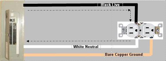
Figure 1a - Basic electrical circuit for an electrical receptacle
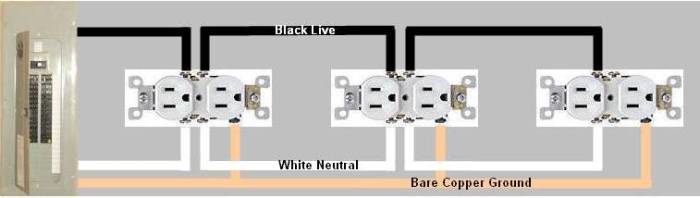
Figure 1b - Multiple electrical outlets (receptacles) on the same circuit are connected in parallel
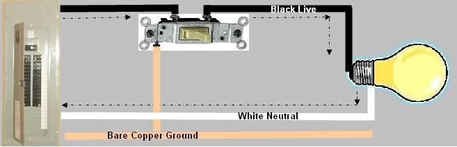
Figure 1c - If we exchange the receptacle for a light, we would require a switch to turn it on and off.
As shown in Figure 1c - the black, live wire has a switch placed in the line. When the switch is in the off position power is interrupted on its path to the light bulb. In the on position, the circuit is complete and current flows from the circuit breaker panel, through the switch and light bulb and then back to the panel on the white, neutral wire.
All items within the circuit are connected to the bare copper ground as a safety system.
For simplicity the power coming into your home is made up of 2 - 120 VAC circuits. This provides the ability to operate electrical devices at 240 VAC which is the nominal voltages for ranges, ovens, water heaters and air conditioners.
Many devices that require 240 VAC also require 120 VAC for operation. A typical wiring diagram for a 240 VAC appliance (range, dryer) would look like Figure 2.
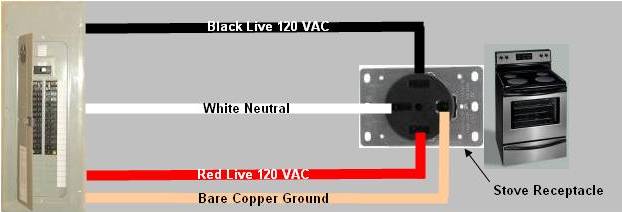
Figure 2 - Typical wiring diagram for a 240VAC appliance or electrical circuit
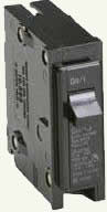
Figure 3 - Single pole circuit breaker
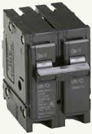
Figure 4 - Double or two pole circuit breaker
A circuit supplying 120 VAC will come through a single pole circuit breaker, (often termed a 1-pole circuit breaker), as shown in Figure 3.
A circuit supplying 240 VAC will come through double pole circuit breaker, (often termed a two 1-pole circuit breaker or a two single pole circuit breaker), (2 - 120 VAC circuits). Some manufacturers build a one piece 2 - circuit breaker, others use 2 120 VAC breakers with a common on/off bar , as shown in Figure 4.
NOTE 1: We use the voltage term of 120 VAC. Many jurisdictions operate on 115 VAC, others on 117 VAC. The method of connection remains the same no matter what the nominal voltage is stated as.
Additional information on installing or replacing an electrical receptacle.
Additional information on stripping and terminating electrical wire.
Additional information on Installing a switch.
Additional information on Installing a 3-way switch.
Additional information on Installing a 4-way switch.
Additional information on Wire sizes.