
- Except for the first section, which is embedded in the walkway or driveway, the sections should start and end at a support post. The outside stringers are then fastened to the upright supports using 3/8 or 1/2 inch carriage bolts or lag bolts. Always use washers.
- The ends of the stringers should be cut at the appropriate angle for the slope of your ramp, as shown in Figure 15.
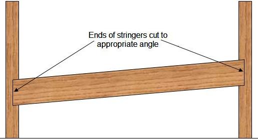
Figure 15 - Cutting appropriate angle for wheelchair ramp stringers
Note: Only stainless steel fasteners should be used.
- Where two sections of ramps meet they should not only be fastened to the upright supports, but should be fastened to one another.
- Bridging is generally not required, however if you are using stringers over 10 feet in length you might wish to consider adding solid bridging in the middle of the ramp section to help keep the stringers straight and equally separated until the floor boards are attached, as shown in Figure 16.
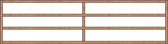
Figure 16 - Solid bridging added to wheelchair ramp stringers
Additional information on bridging
- If a straight through landing is required, it should be a minimum of 60 inches long and the same width as the wheelchair ramp. At a minimum there should be an upright support at all four corners of the landing.
- If a landing is required to change the ramps direction as a "U", it should be a minimum of 76 inches wide (two rams at 36 inches each plus the thickness of the support post), and 60 inches long and again there should be upright supports at all four corners, as shown in Figure 17.
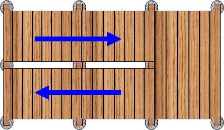
Figure 17 - "U" shaped wheelchair ramp and landing
- If a landing is required to change the ramps direction as an "7", it should be a minimum of 60 inches wide and 60 inches long and again there should be upright supports at all corners, as shown in Figure 18.
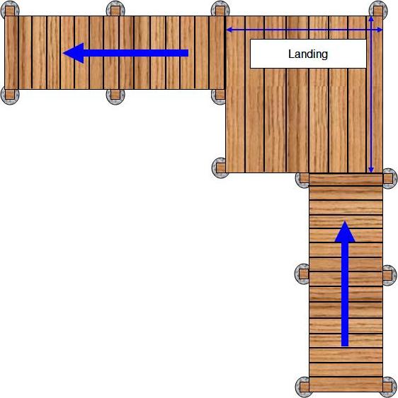
Figure 18 - "L" shaped wheelchair ramp and landing
- The landings are built using the same construction methods that one would use to build a deck.
Additional information on deck construction.
- As with decks, there is no set design for wheelchair ramp railing construction. Figure 19 shows a simple but adequate railing using 2 x 2 uprights fastened to horizontal lumber between the support posts.
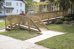
Figure 19 - Simple & adequate wheelchair ramp railing
- Figure 20 shows two different types of railings. On the lower section of the wheelchair ramp the railing is comprised of three horizontal boards running from support post to support post. On the upper section of the wheelchair ramp a traditional railing with vertical boards fastened to horizontal members is used.
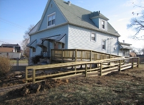
Figure 20 - Horizontal boards between support posts provide a railing on this wheelchair ramp.
- Figure 21 shows a wheelchair ramp, that due to height has multiple "U" turns in order to reach the access door. The railing is traditional, vertical slats mounted to horizontal members. It may be noted that the support structure of the wheelchair ramp in Figure 21 is made of pressure treated lumber and the deck is a composite material.
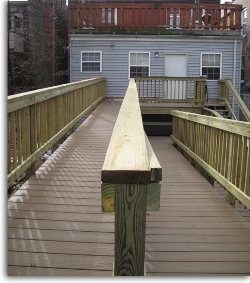
Figure 21 - Traditional railing, vertical slats fastened to horizontal boards
Snow and ice removal from wheelchair ramps