
The vast majority of home electrical receptacles fall into 5 installation categories. The style of the receptacle, standard, Figure 1 or decorator, Figure 2, does not change how it is installed:
- Duplex wall receptacle where both the upper and lower socket are connected together. By far the most common method of connection.
- Duplex wall receptacle where one of the sockets is controlled by a wall switch. This is popular in living (great) rooms and bedrooms for turning on table and floor lamps via a wall switch.
- Single socket receptacles. These are common for electric ranges, laundry dryers, window and wall air conditioners and wall clocks.
- Outdoor Receptacles
- Duplex wall receptacle where one of the sockets is controlled by a wall switch, Figure 1.
Duplex wall receptacle where the upper and lower sockets are split and powered from separate breakers. This is very popular in kitchens to provide more power to countertop appliances.
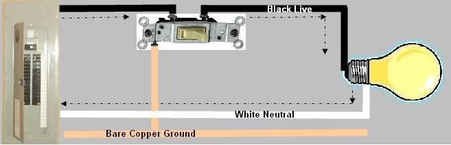
Figure 1 - Plug-in lamp controlled by wall switch
- Turn off power to receptacle at breaker panel. This should be a single pole circuit breaker (Figure 2). Insure that power has been turned off to both sockets by plugging in a lamp or a device such as an electric drill in both sockets (one at a time is acceptable).
- Remove the cover plate, usually held in place with one screw in the center between the sockets. It should be noted that some manufacturers are now making screw-less cover plates which must be pried off with a screwdriver.
- Remove the upper and lower screws that hold the receptacle to the electrical box.
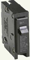
Figure 2 - Single pole circuit breaker
- Pull forward on the receptacle until the receptacle has cleared the box and the wires are extended.
- The receptacle will have the one of the following two wiring configurations.
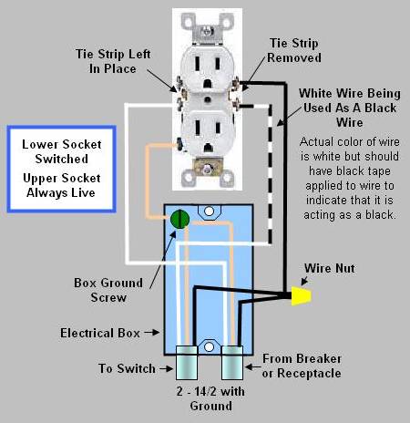
Figure 3 - Duplex wall receptacle (outlets) where the upper socket is always live and the lower socket is switched, (circuit 1).
- One black wire on one of the brass terminal on the side of the receptacle, and a white wire on the the other brass terminal, one white wire on the silver terminal on the opposite side of the receptacle and a bare copper wire connected to a green screw which is integral to the receptacles mounting bracket, see Figure 3.
- The two brass terminals will NOT be connected together, see Figures 4 and 5.
This configuration would indicate that this receptacle is the last device on this circuit.