
- One black wire on one of the brass terminal on the side of the receptacle, and a white wire on the the other brass terminal, one white wire on each of the silver terminals on the opposite side of the receptacle and a bare copper wire connected to a green screw which is integral to the receptacles mounting bracket, see Figure 6.
The two brass terminals will NOT be connected together, but the two silver terminal will have their tie strip intact.
This configuration would indicate that this receptacle is not the last device on this circuit.
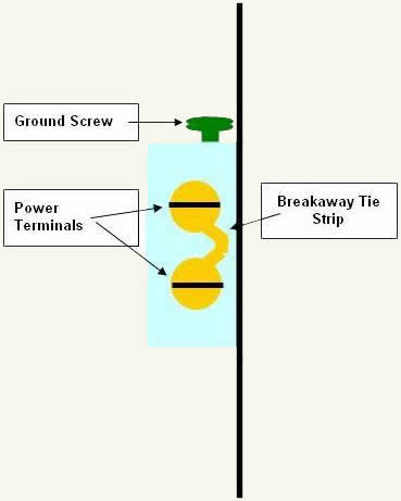
Figure 4 - When purchased, a duplex receptacle will have the breakaway tie strips intact.
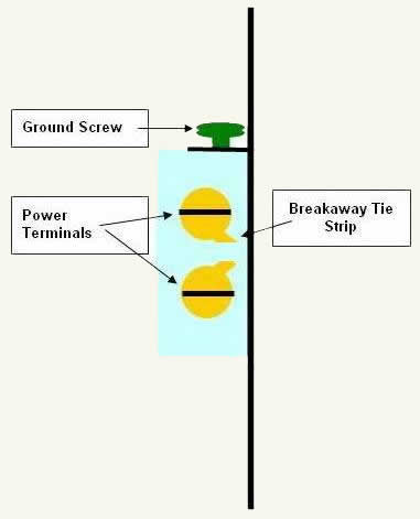
Figure 5 - In order to operate the duplex receptacle from two independent circuits it is necessary to snap the breakaway tie strip(s), separating the upper and lower sockets.
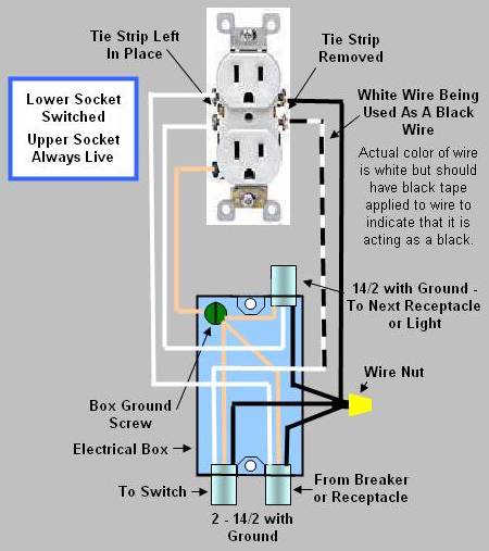
Figure 6 - Duplex wall receptacle (outlets) where the upper socket is always live and the lower socket is switched, (circuit 2).
- Remove the wires from the terminals.
- If there are other wires in the electrical box that are not connected to the receptacle they should be inspected. Make sure that the wire coverings have not been damaged and check all wire nuts to make sure they are tight - tighten if necessary.
- Remove the breakaway tie strip(s) based on which ones were removed on the receptacle that is being replaced.
- Install the wires on the new receptacle.
- One black wire from the wire nut grouping and the white wire from the switch (which is acting as a black and should have black tape applied to the outside of the wire to indicate that it is a black wire) go on the brass terminals, white on the silver and bare copper on the green. Wrap the wire around the terminal screw in a clockwise direction. The insulation on the wire should meet up with the plastic body of the receptacle and the end of the wire should not protrude past the body of the receptacle.
- Do not forget to connect the ground wire to the green terminal.
- Bend the wires and push the receptacle back into the box. Push the wires out of the way of the mounting screw holes. Failure to do this could cause the receptacle mounting screws to push into the wire covering a cause a short circuit. You should be able to push the receptacle into the box to the point where the mounting frame touches the electrical box. Do not use the screws that mount the receptacle to the electrical box to draw the receptacle into the electrical box as this could break the plastic housing on the receptacle.
- Screw the receptacle frame, loosely, to the electrical box. If you have are in a high rise building your electrical boxes may be connected using conduit. If the conduit comes into the electrical box at the top or bottom, it may be necessary to cut the length of the mounting screws so that they do not hit the conduit holding nut on the inside of the box. As an alternative you can use the mounting screws from the receptacle that you removed. Visually inspect the inside of the box to ensure that the screws are not applying pressure to any wires. Align the receptacle so that it is perfectly vertical and tighten the mounting screws.
- Install the receptacle cover plate.
- Turn the double breaker back to the
on
position in the electrical panel.
Additional information on: Wire terminations