
The vast majority of home electrical receptacles fall into 5 installation categories. The style of the receptacle, standard, Figure 1 or decorator, Figure 2, does not change how it is installed:
- Duplex wall receptacle where both the upper and lower socket are connected together. By far the most common method of connection.
- Duplex wall receptacle where the upper and lower sockets are split and powered from separate breakers. This is very popular in kitchens to provide more power to countertop appliances.
- Duplex wall receptacle where one of the sockets is controlled by a wall switch. This is popular in living (great) rooms and bedrooms for turning on table and floor lamps via a wall switch.
- Single socket receptacles. These are common for electric ranges, laundry dryers, window and wall air conditioners and wall clocks.
- Outdoor Receptacles
- Single socket receptacles.
Single socket receptacles are commonly used for electric ranges (Figure 1), laundry dryers (Figure 3), washing machines, window and wall air conditioners (Figures 4 & 5) and wall clocks (Figure 2). In new homes they are also commonly used for microwave and refrigerator receptacles. They come in a variety of socket styles and configurations but for all intent purposes there are just 3 major types:
- 120 VAC
- 240 VAC - 3 Wire
- 240 VAC - 4 Wire
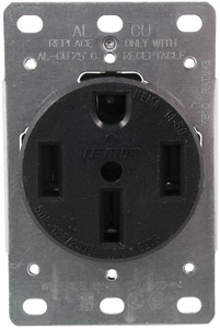
Figure 1 - 240 VAC 50 Amp Flush Mount Range Receptacle. (4 Wire)
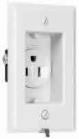
Figure 2 - 120 VAC 15 Amp Clock Hanger Receptacle
Figure 3 - 240 VAC 30 Amp Flush Mount Dryer Receptacle (4 Wire)
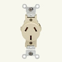
Figure 4 - 120/240 VAC 20 Amp Receptacle (3 Wire)
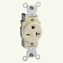
Figure 5 - 120/240 VAC 20 Amp Receptacle (3 Wire)
120 VAC
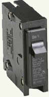
Figure 6 - Single pole circuit breaker
- Turn off power to receptacle at breaker panel. This should be a single breaker, as shown in Figure 6. Insure that power has been turned off by plugging in a lamp or a device such as an electric drill in the socket.
- Remove the cover plate, usually held in place with two screw.
- Remove the upper and lower screws that hold the receptacle to the electrical box.
- Pull forward on the receptacle until the receptacle has cleared the box and the wires are extended.
- The receptacle will have the one of the following wiring configurations.
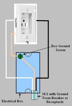
Figure 7 - Wiring a single 120 VAC receptacle
- A black wire on the brass terminal on the side of the receptacle, a white wire on the silver terminal on the opposite side of the receptacle and a bare copper wire connected to a green screw which is integral to the receptacles mounting bracket, as shown in Figure 7. If there are no other wires in the electrical box then this receptacle is the last item on this circuit.
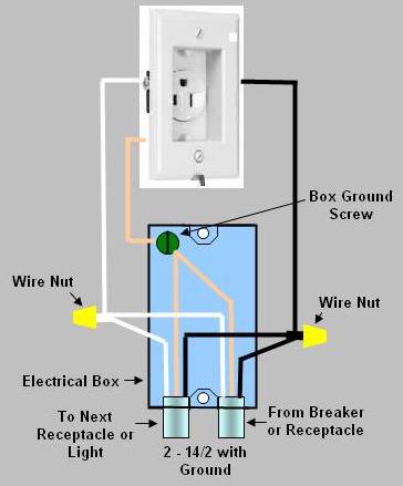
Figure 8 - Installing a single socket receptacle
- If this is not the last device in the circuit then the circuit must continue on. Single receptacles do not have multiple terminal screws. Hence the wires that provide power to devices further along are connected using wire nuts, as shown in Figure 8.
- Remove the wires from the terminals.
- If there are other wires in the electrical box that are not connected to the receptacle they should be inspected. Make sure that the wire coverings have not been damaged and check all wire nuts to make sure they are tight - tighten if necessary.
- Install the wires on the new receptacle.
- Wrap the wire around the terminal screw in a clockwise direction. The insulation on the wire should meet up with the plastic body of the receptacle and the end of the wire should not protrude past the body of the receptacle.
- Do not forget to connect the ground wire to the green terminal.
- Bend the wires and push the receptacle back into the box. Push the wires out of the way of the mounting screw holes. Failure to do this could cause the receptacle mounting screws to push into the wire covering a cause a short circuit. You should be able to push the receptacle into the box to the point where the mounting frame touches the electrical box. Do not use the screws that mount the receptacle to the electrical box to draw the receptacle into the electrical box as this could break the plastic housing on the receptacle.
- Screw the receptacle frame, loosely, to the electrical box. If you have are in a high rise building your electrical boxes may be connected using conduit. If the conduit comes into the electrical box at the top or bottom, it may be necessary to cut the length of the mounting screws so that they do not hit the conduit holding nut on the inside of the box. As an alternative you can use the mounting screws from the receptacle that you removed. Visually inspect the inside of the box to ensure that the screws are not applying pressure to any wires. Align the receptacle so that it is perfectly vertical and tighten the mounting screws.
- Install the receptacle cover plate.
- Turn the breaker back to the
ON
position in the electrical panel.